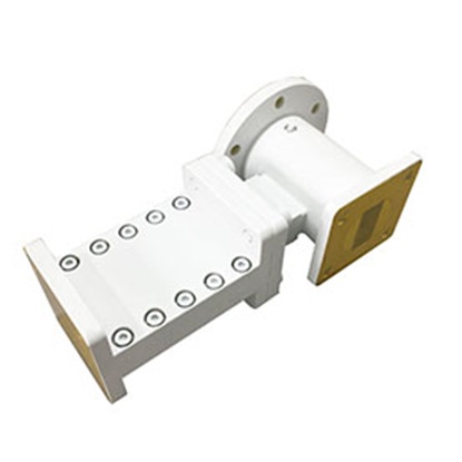
ANTENNA FEEDS & RF NETWORKS

مصنوعات کی وضاحت
ANTENNA FEEDS & RF NETWORKS
Dolph Microwave offers the high performance and high quality antenna feeds and RF networks to enable satcom antenna to offer the best performance. The antenna feed and RF networks are all components combination of antenna used for RF waves receiving and Transmitting. The antenna feed is portion of the antenna ranging from the Tx range to the receive range. The antenna waveguide feed includes transforming the RF waves into electrical signals and transmitting them to the receiver components. So it is namely used for the conversion RF waves into the electric signals.
Types of Antenna Feeds & RF Networks
Antenna feeds and RF networks as the heart of antenna system from Dolph Microwave is R&D by experienced our engineers who engaged into satcom and RF field for years. The components can be offered including OMT, duplixer, filter, phase shifter and feedhorn etc. covering different bands like C-band, Ku-band, Ka-band, S-band. X-band and required dual band etc. Any requirement, please contact sales@dolphmicrowave.com
Microwave Diplexers
OMT (Orthogonal Mode Transducer)
Waveguide Filter
Microwave Phase Shifter
Microwave Feedhorn
Antenna Feed Point Impedance
For an antenna feeds design, the efficiency, gain, and absolute gain are very important.
The feed impedance includes the loss resistance and the radiation resistance. The loss resistance is offered by the antenna components and the feed impedance is at the input of the antenna to the signal. Thus, the loss and the feed impedance must work together to achieve antennae feed normally work.
The radiation resistance is offered by the antenna to the radiation power namely the dissipated radiation power.
Measuring Antenna Feeds Point Impedance
The feed point impedance of an antenna is a crucial parameter that reflects its input impedance at the feeding point. Several methods exist for measuring this impedance, including:
Standing Wave Method: This method utilizes a standing wave meter to measure the standing wave ratio (SWR) on the antenna. Then, based on the SWR, the feed point impedance can be calculated. While simple and readily available, this method offers limited accuracy and is best suited for antennas with subtle impedance variations.
Short Circuit Method: A short-circuit ring is placed near the antenna's feed point, and the input impedance is measured. This method offers good accuracy but requires placing the ring close to the feed point, which might affect the antenna's radiation characteristics.
Open Circuit Method: Similar to the short circuit method, but an open-circuit termination is used instead. This method also offers good accuracy but suffers from potential impacts on the antenna's radiation due to the open termination close to the feed point.
Vector Network Analyzer (VNA): Utilizing a VNA provides the most accurate measurements but comes with a significantly higher cost and requires more complex operation.
The choice of method depends on factors like antenna type, required accuracy, and cost considerations.
Here are some key points to remember when measuring antenna feeds point impedance:
Measurement environment: Minimize electromagnetic interference in the surrounding area.
Measurement equipment: Ensure the equipment's accuracy meets your requirements.
Measurement method: Follow the chosen method's procedures meticulously.
Here are general steps for measuring antenna feeds point impedance:
Mount the antenna appropriately.
Connect the measurement instrument to the feed point.
Set measurement parameters.
Conduct the measurement.
Record the results.
How Feed Point Impedance Affects Antenna Performance
The feed point impedance of an antenna significantly impacts its various performance aspects:
Standing Waves: Mismatch between the feed point impedance and the feedline's characteristic impedance leads to standing waves on the antenna. Higher standing waves translate to lower power transfer efficiency and increased losses.

