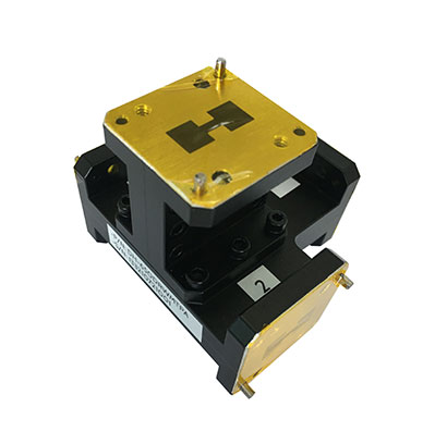
Double Ridged Waveguide Tees

Descripción del producto
Dolph Microwave provides a series of high-performance waveguide tees, power divider, and combiner products. By connecting a load to the E and H plane tee , it can be made into a Magic T power divider or synthesizer. The magic tee in microwave engineering has the characteristics of opposite port isolation, adjacent 3 dB coupling and perfect matching, which makes wave guide tees widely used in the microwave field, especially used in monopulse radar and difference comparator, radar transceiver switch, power distribution/combination, mixed Frequency converter and phase shifter.
Waveguide E And H Plane Tees Ordering Guide
Ordering Guide of Double Ridged Waveguide Tees
Flange type: Multiple types of waveguide tee in microwave available - see Dolph Microwave Flanges page.
Finish: Corrosion protection plus black top coat of our magic tee microwave in microwave engineering.
E Plane and H Plane Waveguide Tees Datasheet
Magic Tee Diagram
Magic T waveguide are widely used as hybrid circuits in microwave impedance bridges, balanced mixers in receivers, and frequency
discriminators.
The structure is composed of an E-plane branch and H-plane branch coupled with each other, providing good impedance characteristics and
symmetric property over the entire frequency range.
E-plane and H-plane waveguide has been designed to minimize the leakage of RF wave between the E-plane and H-plane branches with other waveguide ports perfectly matched.
Details Of Waveguide Magic Tees In Microwave Engineering
Waveguide Tee In Microwave Advantages
Double-ridged magic T waveguide can provide more bandwidth than "normal" rectangular waveguide Magic T.
Application Of Waveguide Tees
1. Measure the impedance
A null detector is connected to E-Arm port while the Microwave source is connected to H-Arm port. The collinear ports together with these ports make a bridge and the impedance measurement is done by balancing the bridge.
2. As a duplexer
The duplexer is a circuit which works as both the transmitter and the receiver, using a single antenna for both the purposes. Port 1 and 2 are used as receiver and transmitter where they are isolated and hence will not interfere. An antenna is connected to E-Arm port. A matched load is connected to H-Arm port, which provides no reflections. Now there exists transmission or reception without any problem.

