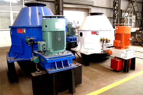
Vertical Centrifuge

產品說明
The vertical centrifuge machine is made up of the screen which diameter range from 700 to 1,000 mm , the rotor body (including the blade), transmission, body, lubrication system, etc.
Application of Vertical Centrifuge Machine
The vertical centrifuge is fit for material dehydration, generally used for coal, salt and other materials. Our coal centrifuge has helped a lot of customers with their industrial projects.
Working Principle of Vertical Centrifuge Machine
Wet materials are feed into the mouth of industrial centrifuge machine, then are accelerated by the rotated distribution cone and move rapidly towards the space between screen and rotor. With the centrifugal force, the smaller particles of material get closed to the screen surface, liquid and part of the particle size of less than 0.5 mm of material get across the material space and screen gap, then are thrown out of the screen, the larger particles of materials soon slipped into spiral nesting mouth along the screw blade with the action of gravity and centrifugal force fine material attached to the screen surface are discharged by the scraper centrifuge through blade action, while the liquid through the screen and fine materials are thrown into the water tank then outflow through the drain, so as to achieve a solid-liquid separation.
Technical Performance Parameters of Vertical Centrifuge Machine
Serial No. Part Name Unit. Numerical Value
1 Feed size mm 0~25
2 The screen cloth m2 1.88
works area
3 Handling capacity per hour t/h 140~200
4 The percentage of product water discharge % 5~8
5 Strainer big end diameter mm 1200
6 Strainer slit mm 0.5
7 Main electrical machinery Model Y280S-4-V1
Power KW 75
Rotating speed r/min 1480
8 Lubricates the electrical machinery Model Y90L-4
Power KW 1.5
rotating Speed r/min 1400
9 External dimensions mm 3160×2460×2680
Long × wide × high
10 Gross weight kg 9121
Installation and Testing of Vertical Centrifuge Machine
When the centrifuge is assembled completely in the manufactory, the test should be carried out in air operations. It should be sent out to the users in the form of machine after it is up to the requirements, the users can directly follow the steps to install the equipment when they get receipt of it.
1. Installation Step
1) Check whether the basis of surface is level, if it is uneven, adjust the leveling pad. Check the ground pin-hole size and pore size of the centre. Check whether the basis of elevation to meet the requirements.
2) Mount the shock absorber to the ground pin holes, install the nut first but not tightened until the machine is in the right place, then solid-tight.
3) Hoisting the machine in the place, tighten anchor bolts, tighten the upper pairs of nuts before the measurement with the caliper pad diameter, it is required that the diameter of compact size should be increased 2~3mm than the first fasten one.
2. Test Step
1) Checked before testing items
a. All bolts connections should be tighten.
b. There is no equipments which have effects on the machine operation.
c. Make sure the pulley can be moved with both hands so that the machine can be rotated flexibly with non-stuck and abnormal noise.
d. Make the belt hang right.
e. Indicator within the oil tank should be located in the groove between the upper and lower limits.
2) Commissioning and inspection of the project
Meet the above requirements, follow these steps, and start running in the air for 8 hours.
a. Open the oil pump motor.
b. Observe the oil supply situation, make sure everything is ok, open the console.
c. While there is no abnormal noise, stable operation, measure the amplitude of the centrifuges in the horizontal plane and make sure that it is less than 0.3mm.
d. Measure the oil temperature every 30 minutes, ensure the oil temperature rising is no more than environmental temperature-30℃.

