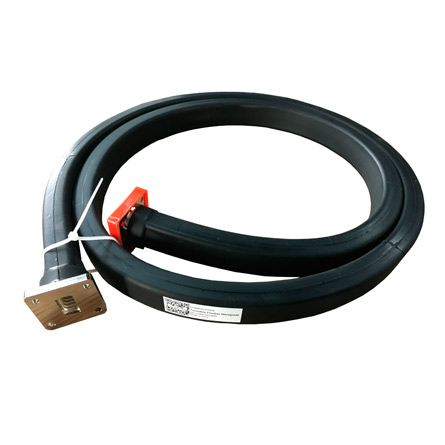
Flexible Waveguide

Descripción del producto
As one of the most professional flexible waveguide manufacturers, Dolph Microwave manufactures a quality line of flexible twistable/non-twistable waveguides, specially designed to meet all of your requirements. The components is made from a helically wound waveguide core and additional mechanical support is offered from a variety of protective jackets.
Flexible Waveguide Definition
The Flexible Waveguide is parts of Feeder line, compared with the rigid waveguide, which is not only reduces the difficulty of connection, but also keep connection accuracy. The Rectangular Flexible Waveguide has E bend and H bend function including twisted function.
Flexible Waveguide Ordering Guide
Flexible Twistable Waveguide Ordering Information
Flexible Non-twistable Waveguide Ordering Information
Flange type: Multiple types available - see Dolph Microwave Flanges page.
*The Standard Model Numbers above are the most common parts ordered for size, material and flange. However, these models can easily be altered to accommodate your needs by using the Model # code system below for complete part number.
** Please refer to the Technical Reference section for flange types/connectors details. Please contact us for your specific requirements.
Flexible Waveguide Definition
Dolph flex waveguide 350w refers to a crucial component in microwave engineering, specifically designed to connect rigid waveguide systems when precise positioning is challenging. Unlike rigid waveguides, which are employed in equipment rooms and for final assembly points, flexible waveguides offer adaptability in scenarios where exact alignment is unattainable.
These waveguides are constructed as thin-walled structures with folds, allowing them to bend along the H-plane, E-plane, and twist at 90º or 45º angles. Remarkably, they can undergo these variations simultaneously, offering a versatile solution for complex transmission needs. The primary purpose of flexible waveguides lies in their ability to guide specific frequency electromagnetic waves while accommodating bends and twists.
Beyond their flexibility, these waveguides also serve to isolate vibrations, address installation challenges arising from misalignments, and facilitate easier positioning and alignment. The incorporation of metal structures with mechanical and electrical interconnections forms hollow channels that exhibit waveguide behavior, contributing to their efficacy in various applications.
Dolph waveguide components supplier, their flexible Waveguide emerges as a vital element in microwave transmission, providing a dynamic and adaptable solution for scenarios requiring precise waveguide connections with bending and flexing capabilities.
Flexible Waveguide Diagram
Flexible waveguide use mechanically and electrically interlinked metallic structures to form a hollow channel that behaves as a waveguided with enhanced flexible and somewhat reduced performance. As the interlinked metallic structures, even if soldered and crimped, are not perfectly smooth conductive walls, the performance of flexible waveguides will not likely reach that of a traditionally manufactured waveguide. That being said, the flexible nature of these waveguide allows them to be used in applications for which rigid waveguide structures may be too bulky, unfit for the complexity of the geometries, too heavy, take too long to design/assemble, or may be unavailable during emergency repairs or retrofitting operations.
Flexible Waveguide Options
Flexible Waveguide Type: Twistable or non-twistable.
FlexibleWaveguide Size: WR137, WR112, WR90, WR75 or others.
Insertion Loss and VSWR: unit in dB.
Flexible Waveguide Length: 300, 500, 900, 1200, 1800 or other length in mm.
Flange type: Flat or groove or chock.
Hardware kits: Required or self preparation.
Any special requirement, please offer the drawing or dimension for checking.
Dolph Microwave also offer seamless waveguide with double rigid flexible design.

